Imagine a bicycle with flickering strips of them, sliding along foggy Carrboro roads at night like a bioluminescent deep-sea cephalopod!
That's what I said when I first got started with the NeoPixel ring. Well, we also have a 60-pixel strip. This is an opportunity to learn some electrical engineering, develop some cool neopixel effects, and keep me illuminated while I'm biking around at night.
The first step was to lift the control circuit off the breadboard and onto a more permanent printed circuit board. This was my first experience with the process of PCB design and fabrication, so I spent a lot of time watching the DigiKey guide to KiCad software. The PCBs were printed in a facility and we have several copies now, which will be helpful for the next project of this sort.
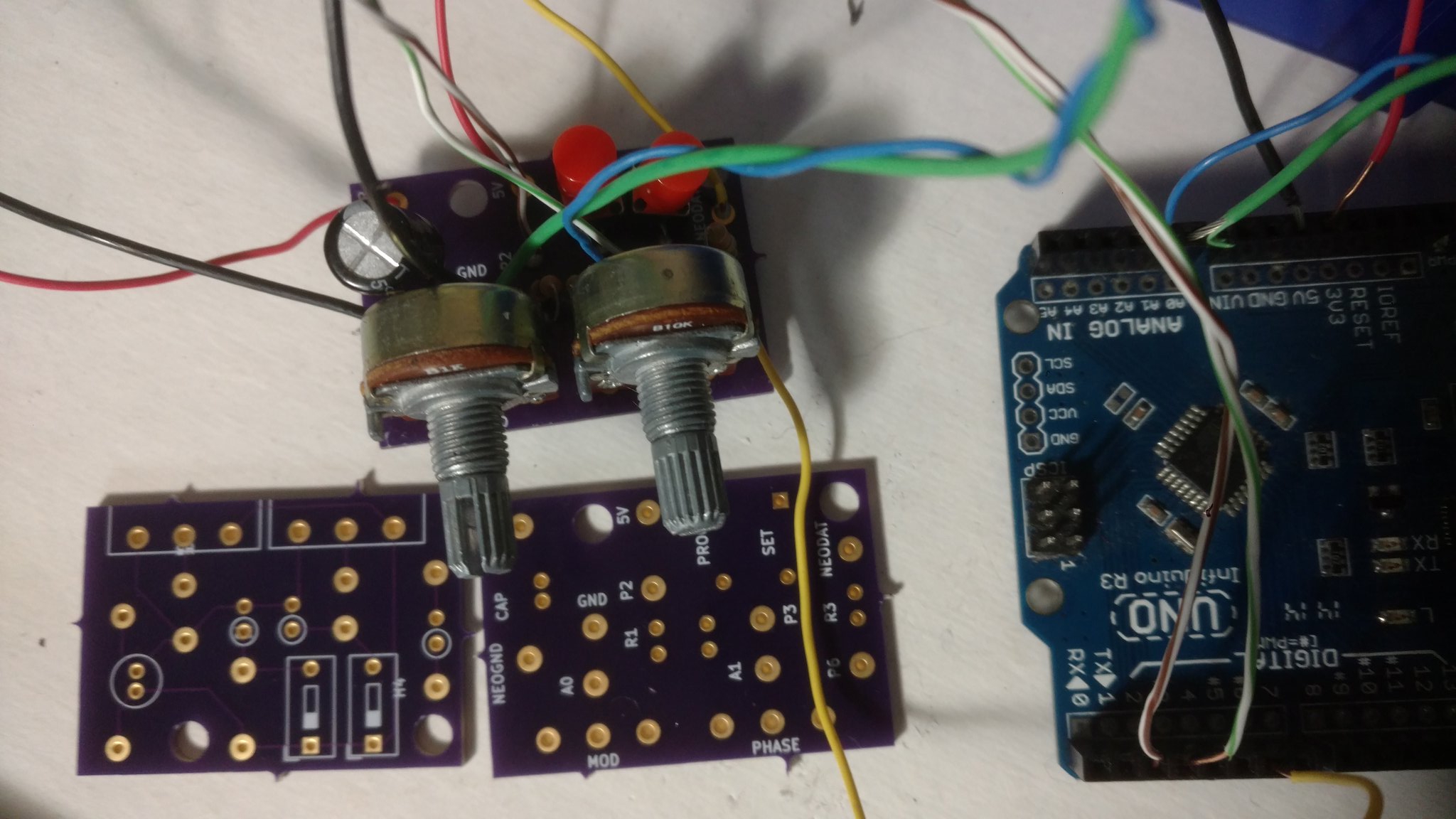
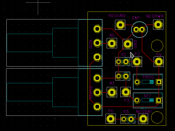
I don't want a monotonous light pattern; I want to be able so select among them. So, I need at least one button to increment the pattern program. While we're adding control buttons, let's add another - this will act as a second discrete control. Might as well add two potentiometers to act as continuous analog controls. The rest of the circuit follows the adafruit uberguide. Finally, there's a global power on/off switch.
The code framework for the arduino is pretty straight forward: There's variable and pin initialization and the interface with the neopixel strip is set up. One detail is that, to override the pattern loop, the button pins are set as interrupts. I don't fully understand this! I am also not following best-use advice, because I can't get it to work correctly.
  #include <Adafruit_NeoPixel.h>
  #define PIN 6
  #define NUM_LEDS 60
  Adafruit_NeoPixel strip = Adafruit_NeoPixel(NUM_LEDS, PIN, NEO_GRB + NEO_KHZ800);

  //dial one, PROG
  const int analogInPin0 = A0;  // Analog input pin that the potentiometer is attached to

  //dial two, SETT
  const int analogInPin1 = A1;  // Analog input pin that the potentiometer is attached to

  const byte ledPin = 12;
  const byte interruptPin = 2;
  const byte interruptPin_sec = 3;
  volatile byte state = HIGH;

  int arr = 0;
  int gee = 0;
  int bee = 0;


  int sensorValue = 0;        // value read from the pot
  int outputValue = 0;        // analog reading

  volatile int prog = 0;
  volatile int setting = 0;

  int mod = 5; //number of programs to switch between

  void setup() {

    strip.begin();
    strip.show(); // Initialize all pixels to 'off'
    strip.setBrightness(25);

    pinMode(interruptPin, INPUT_PULLUP);
    attachInterrupt(0, blink, RISING);
    pinMode(interruptPin_sec, INPUT_PULLUP);
    attachInterrupt(1, wink, RISING);

  }

  void loop() {

    switch(prog % mod){

      case 0:
        nightVision();
        break;

      case 1:
        arr = random(255);
        gee = random(255-arr);
        bee = 255-arr-gee;
        Twinkle(arr,gee,bee);
        break;

      case 2:
        blaster( );
        break;

      case 3:
        switch(setting % 2){
          case 0:
            Strobe(255,0,0,random(3));
            Strobe(0,255,0,random(3));
            Strobe(0,0,255,random(3));
            break;
          case 1:
            arr = random(255);
            gee = random(255-arr);
            bee = 255-arr-gee;
            Strobe(arr,gee,bee,3);
            break;
        };break;

      case 4:
        switch(setting % 2){
          case 0:
            rainbowCycle();
          break;
          case 1:
            VaporWave();
          break;
        };break;

      default:
      break;
    }
}

  void blink() {
    state = !state;
    prog = (prog+1)%mod;
  }

  void wink() {
    state = !state;
    setting +=1;
  }
The sketch above outlines the implementation: a counter called prog is kept, and when the first button is pressed, it is incremented; this is used to track which light pattern is selected. This happens in the switch/case tree in the loop() function, where a function like nightVision or Twinkle is run depending upon the modulus of the prog count.
void nightVision(){
    for(int j=0; j%lt; 10; j++){
    sensorValue = analogRead(analogInPin0);
    int intensity = map(sensorValue, 0, 1023,16, 255);
    setAll(intensity, 0, 0);
    showStrip();
    delay(50);
    if (state){  state = !state;break;};
  }
}
Here's the first program, a simple dimmable red that will be easy on the night vision when you first turn the unit on. The reading from one of the potentiometers is mapped to a value for the red channel of the RGB light. One subtlety is the for loop and the if-break routine. The state variable is set to True when either of the buttons are pressed. This exits from the nightVision() function, and the loop() moves to the next iteration. This is how we switch color patterns with a button press.
void Twinkle(byte red, byte green, byte blue){
  sensorValue = analogRead(analogInPin1);
  int twinkleCount = map(sensorValue, 0, 1023, 1, 32);

  for (int i=0; i %lt; twinkleCount; i++){
    setPixel(random(NUM_LEDS), red, green, blue);
    showStrip();
    sensorValue = analogRead(analogInPin0);
    int twinkleDelay = map(sensorValue, 0, 1023, 1, 50);
    delay(twinkleDelay);
    if (state){  state = !state;break;};
    }
  if(setting%2==0 ){
    setAll(0,0,0);
  }
}
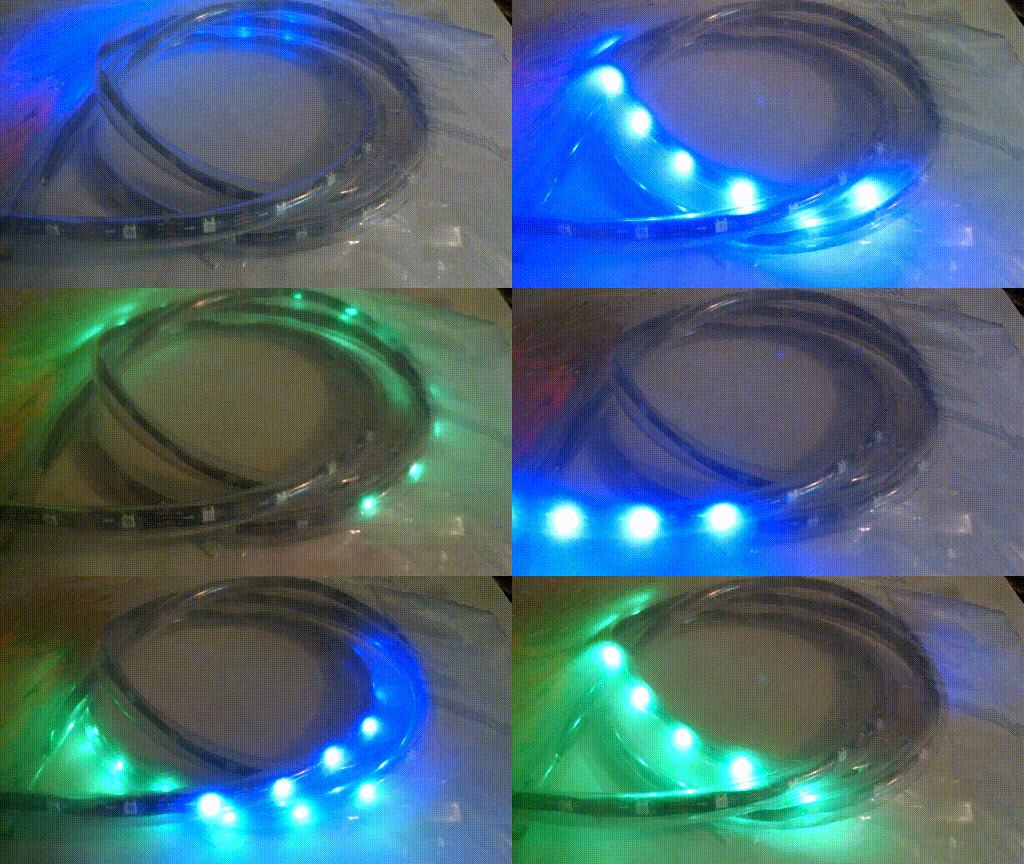
This project was partly inspired by this HackADay-featured collection of effects, and the next program in the queue, Twinkle, is based directly on one of theirs. The core of the Twinkle function is the repeated setPixel(random(NUM_LEDS), ...) call, which assigns a given color to a random LED each time it's invoked. On top of the original core, there are some modifications: the time between individual sparkles (twinkleDelay) is set by the first potentiometer. The actual number of the sparkles (twinkleCount) is set by the other potentiometer. This pattern also makes use of the second button to toggle whether the strip is blanked (ie, all pixels set to 0). If the second button is pressed, this is turned off. The pixel stays at its last set color until it is randomly overwritten.
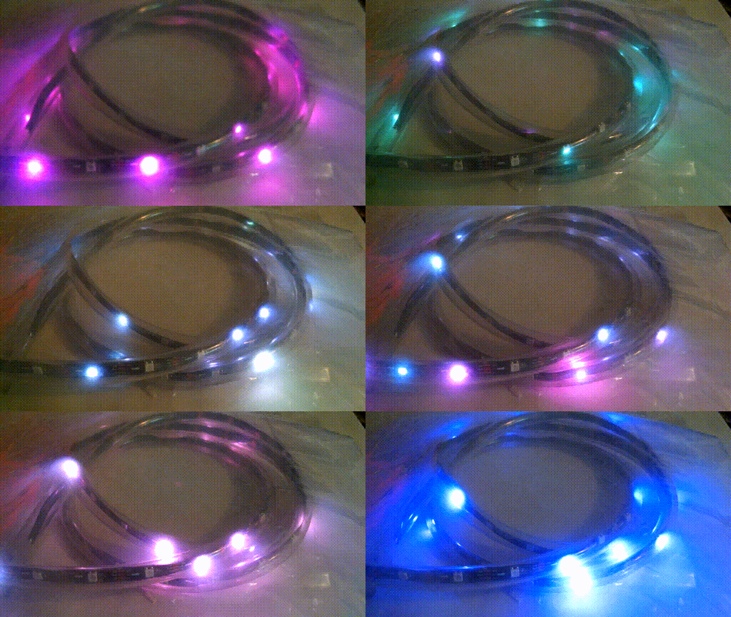
To keep things interesting, the Twinkle function is called with a random color with each pass of loop(). Originally this was implemented by calling a random number between 0 and 255 independently for each of the red, green, and blue channels. This works well enough, but the palette it generates tends to be more pastel than I'd necessarily like. To make the colors more vivid, random colors were generated here by assuming that there are 255 total color points to assign, and distributing them randomly across the three channels.
   case 2:
      if(setting % 2 == 0){
        rainbowCycle();
        break;
       }
      if(setting % 2 == 1){
        VaporWave(50);
        break;
      }
      break;
//  ....


void VaporWave(int WaveDelay){
  int Position=0;
  for (int j=0; j %lt; NUM_LEDS*2; j++){
    Position++;
    for(int i = 0; i %lt; NUM_LEDS; i++){
      setPixel(i, (sin((i+Position)*180/3.14)*127+128), 0, 127);
      showStrip();
    }
  outputValue = map(sensorValue, 0, 1023, 0, WaveDelay);
    if (state){  state = !state;break;};
      delay(outputValue);
  }
}
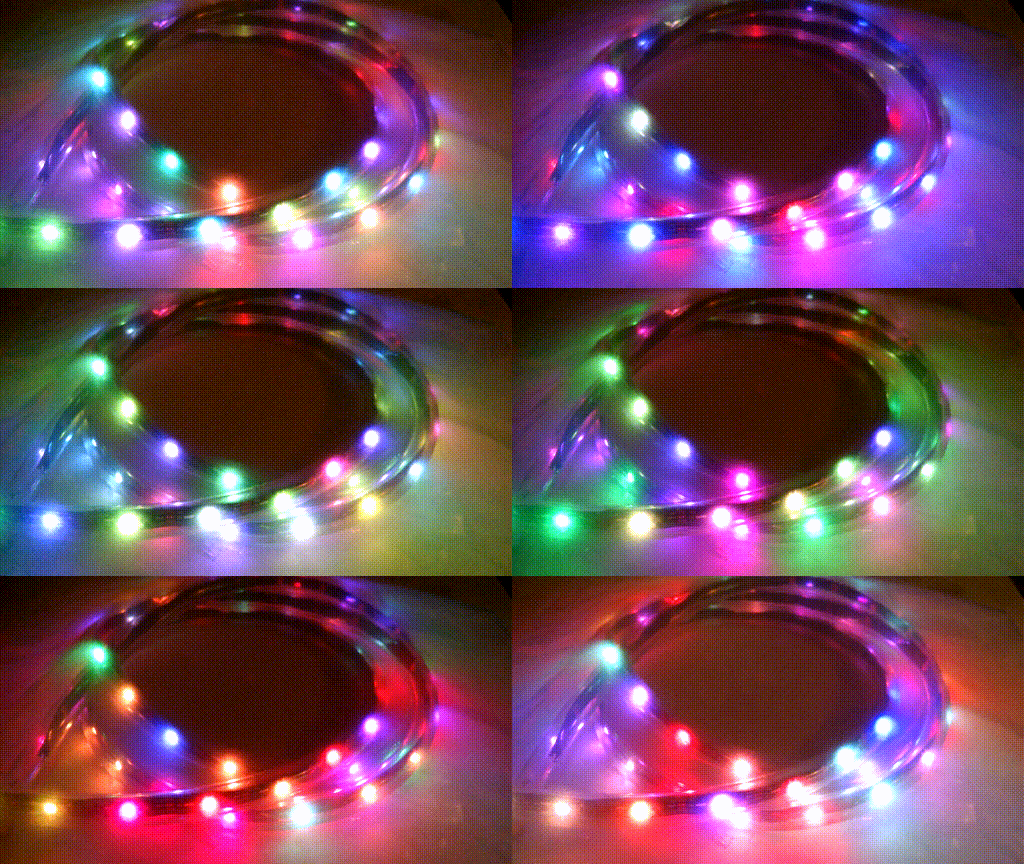
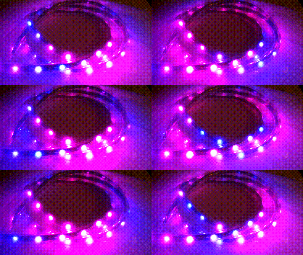
The next program is a pair of cycling color routines. The first was a rainbow cycle adapted from an example script from the adafruit NeoPixel library, modified to have the cycle speed controlled by the first potentiometer. The other one, VaporWave, is an original of mine. Each pixel has its blue channel set to 127 of 255, and it's green channel set to 0. Then, the red channel is set according to a sine wave with a maximum of 255 and a minimum of 0.
    case 3:
      switch(setting % 2){
        case 0:
          Strobe(255,0,0,random(3));
          Strobe(0,255,0,random(3));
          Strobe(0,0,255,random(3));
          break;
        case 1:
          for (int i = 0; i%lt;3; i ++ ){
            arr = random(255);
            gee = random(255-arr);
            bee = 255-arr-gee;
            Strobe(arr,gee,bee,3);
          }
    break;
  }

// ...

void Strobe(byte red, byte green, byte blue, int StrobeCount){
  sensorValue = analogRead(analogInPin0);
  int FlashDelay = map(sensorValue, 0, 1023, 50, 250);
  for(int j=0; j%lt; StrobeCount; j++){
    setAll(red, green, blue);
    showStrip();
    delay(FlashDelay);
    setAll(0,0,0);
    showStrip();
    delay(FlashDelay);
    if (state){  state = !state;break;};
  }
delay(FlashDelay*2);
}
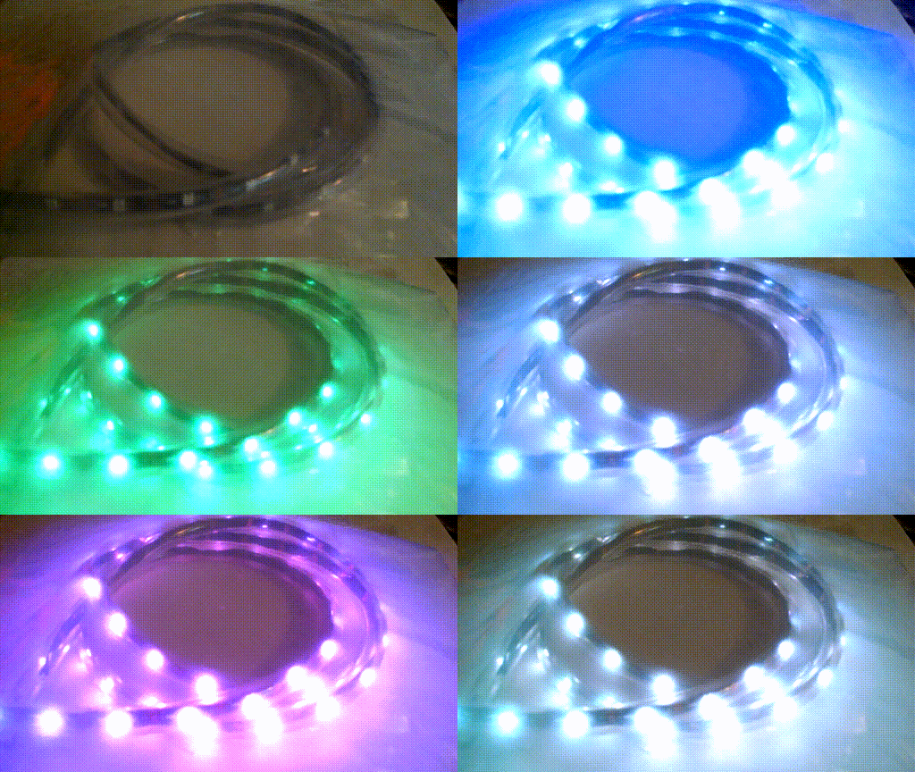
The next pattern is also a modification of a tweaking4all routine, which accepts a color and flashes it several times. A potentiometer read controls the rate of the flashing, and the setting button toggles between two schemes: in the first, red green and blue are each flashed a random number of times; in the second, a random color is flashed three times.
    case 4:
      blaster();
    break;
//  ...

void blaster( ){
  for(int j=0; j%lt; 10; j++){

  sensorValue = analogRead(analogInPin0);
  int interval = map(sensorValue, 0, 1023,1, NUM_LEDS/4);

  int red = 0;
  int green = 0;
  int blue = 0;
  int col = random(1,4);
  if (col==1){
    red = 255;
  }
  else if (col==2){
    blue = 255;
  }
  else{
    green = 255;
  }

  int StartPoint = random(1, NUM_LEDS);

  for( int i = 0; i %lt; interval; i++){
    setPixel((StartPoint + i)%NUM_LEDS, red, green, blue);
  }

  showStrip();
  sensorValue = analogRead(analogInPin1);
  int blastDelay = map(sensorValue, 0, 1023,15, 1000);
  delay(blastDelay);
    if(setting%2==0 ){
      setAll(0,0,0);
    }
    if (state){  state = !state;break;};
    }
}
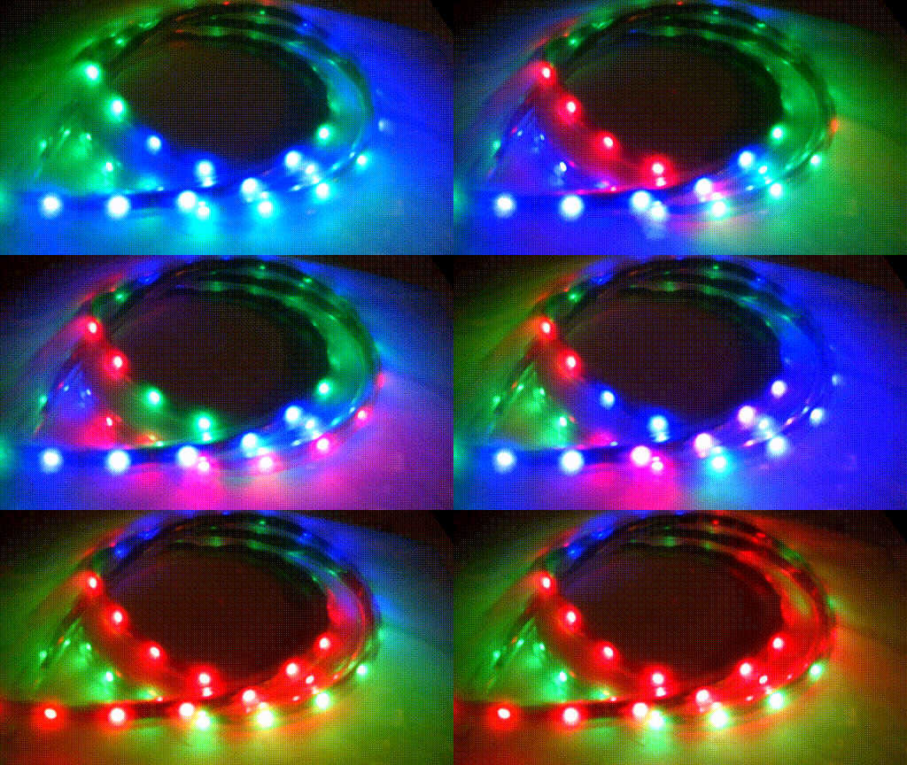
This last pattern is a heavily modified version of the tweaking4all Cylon program. In each cycle, a potentiometer is read and the result converted into an interval length. A random color is chosen from among red only, blue only, and green only. A point on the chain is selected at random, the next several pixels are colored. The actual number, interval, is controlled by one potentiometer; the other controls blastDelay, which determines the wait time until the next block is written. The overall effect is of random chunks of light flashing off and on. This routine also makes use of the setting button, which toggles the end-of-loop blanking. When this is turned off, the colored bars pile up on each other, like a chunkier version of the Twinkle effect.
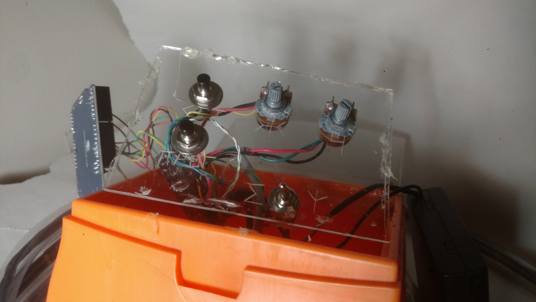
The circuits were wired up, and the whole thing put in a mostly water-tight container, including a vinyl tube to house the NeoPixel strip. Right now the lights are just sort of wrapped around the bike like a rope. This works well enough, but a future modification will probably break the strip into subsegments with specific locations on the bike, such as horizontal strips on the sides and vertical ones on the front/back. This change of topology will require some rethinking of how the pixels are addressed, but it will also permit new patterns. For example, with pixels arranged in space rather than just sequence, you could create a consistent gradient. Putting blue at the front of the bike and red in the back would simulate the doppler effect of an object moving at relativistic speeds, with the intensity of the redshift controlled by potentiometer.
